
Wireless irrigation control
Irrigation control anywhere there is water, even where there is no power.
A battery or solar powered LoRaWAN controller at the valve runs the solenoid, meters the water and reports to one platform. No 120 V feed, no wire back to a cabinet, no cellular plan per zone. Medians, parks, streetscapes and campuses come back under control.
Latching solenoid control, pulse flow metering and pressure on one network.
At a glance
What one wireless controller replaces.
Where it makes the most sense
Commercial sites where the wire is the problem.
Wireless control is a design decision for the zones a cabinet cannot reach economically. These are the ones we see most on commercial and municipal projects.
Roadway medians and rights of way
No power, traffic control for every wire repair, and a controller that is commissioned from the shoulder in minutes.
Parks, trails and pocket parks
Water service exists, power does not, and the nearest cabinet is across a road or a creek.
Streetscapes and planters
Zones added to a block long after the original controller, or orphaned when a utility moved the cabinet.
Campuses and HOA common areas
Many small zones across many parcels, with consumption reported per parcel for cost recovery.
Cut-wire and abandoned zones
Controller wire severed by road work or construction years ago. The valves are fine; only the wire is gone.
Remote water sources
Ponds, wells, hydrant meters and reclaimed water points of connection that were never worth trenching to.
The zones a wired controller cannot reach
Every commercial landscape has them. The center median on the arterial, where the controller wire was cut during a road widening and never replaced. The pocket park with a water service but no power. The streetscape planters that were designed with irrigation and then abandoned when the nearest cabinet went away. A zone with no wire is a zone nobody can schedule, meter or audit, so it is either watered by hand, watered by a timer nobody can see, or not watered at all.
Wireless irrigation control removes the wire from the design. A battery powered or solar powered controller sits at the valve, opens and closes a standard latching solenoid, counts pulses from a flow meter on the same assembly, and talks to the rest of the system over LoRaWAN. There is no 120 V feed, no conduit back to a cabinet, and no cellular subscription per valve. The controller joins a private network that the same gateways carry for soil moisture, pressure and weather sensors, and the schedule lives in one place: the application.
How the data moves, hop by hop
The whole path has four parts. It helps to know which one owns which job, because it tells you where a problem lives when a zone does not run.

1. The field assembly
The controller mounts to a post or the wall of the valve box, wired to a DC latching solenoid on the existing valve. A latching solenoid needs no continuous power: one short pulse opens it, one closes it, and it stays put in between. The controller has two solenoid outputs, so one unit runs two valves, and two general purpose inputs. The first input usually counts pulses from a flow meter, so every gallon through the valve is recorded at the source. The second can read a valve position switch, which confirms that a command actually moved the valve rather than assuming it did.
A pressure transducer on the backflow or riser is a separate LoRaWAN device, but it reports on the same network to the same screen, so pressure, flow and valve state for a zone line up in one record.
2. The gateway
The gateway is a radio receiver on a roof, a light pole or a cabinet, typically within a mile or two of the valves in a built-up area and much farther across open ground. It hears every LoRaWAN device in range on eight channels at once, stamps each packet with signal strength, signal quality and time, and passes it on over whatever backhaul the site has: Ethernet, Wi-Fi, cellular, or a point-to-point wireless bridge. It carries traffic in both directions but makes no decisions. If two gateways hear the same valve, both forward the packet, which is how coverage overlap becomes redundancy at no extra cost.
3. The network server
The network server is the LoRaWAN control plane. It checks the join request against the device's identifiers and key, deduplicates packets that arrived through more than one gateway, handles the network layer of encryption and the MAC commands that tune each device's data rate and transmit power, and hands the device its clock after it joins. Most importantly for control, it queues downlinks and delivers each one in the device's next receive window. It never sees the application payload in the clear: valve commands and meter readings are encrypted end to end between the controller and the application.
4. The application
The application is where the bytes become irrigation. A decoder turns the payload into valve state, gallons, flow rate, pressure and battery percent. Schedules are written here and pushed down to the controller. Alerts fire on the conditions a superintendent cares about: flow with the valve closed, no flow with the valve open, low pressure, low battery, a controller that stopped reporting. Consumption rolls up by zone, by site and by month for the owner's water report. MODURA does all of this, and the same data is available to any other platform over MQTT, a webhook or the API.
Getting a command to a valve
Uplinks are simple: the controller reports on its own schedule, every 20 minutes by default and anywhere from every minute to every 18 hours, plus an immediate report whenever a valve changes state. Downlinks work differently, because a battery device cannot listen all the time.
We deploy the controller as a LoRaWAN Class A device. After each uplink it opens two short receive windows, then sleeps until the next report. A command from the application waits in the network server's queue and is delivered in the next window, so the wait for a manual command is set by the reporting interval. To make manual control quicker without shortening the data reports, the controller has a separate response-time setting: it sends a small blank uplink at that interval purely to open a window. A five minute response time is the usual choice for a median, which puts a manual run from a phone within five minutes of tapping it while keeping the multi-year battery life.
The practical rule: schedules do not care about latency, because they run on the controller. Only manual runs wait for a window, and a technician standing at the zone rarely needs the valve faster than the next window. Class A is what keeps a controller running for a decade on the cells it shipped with, and it is the mode every model of the controller supports.
Schedules live on the controller
The controller stores up to 16 schedule plans in its own memory. Each plan has a start time, an end time, the days of the week it repeats, the valve it controls, and an optional water volume in meter pulses. A plan ends when either the time or the volume is reached, whichever comes first, so a zone can be told to take 500 gallons rather than 20 minutes and it will stop at 500 gallons even if the pressure was high that morning.
Because the plans are on the device, a run happens whether or not the network is up. A gateway power outage or a backhaul failure delays the reporting, not the watering. The network server keeps the controller's clock accurate, and a rain delay from the application pauses the plans without erasing them. Volume based plans need the flow meter wired to the pulse input; time based plans work with no meter at all.
The controller in detail
We deploy a commercial LoRaWAN solenoid valve controller that has been in production for several hardware generations. The figures below are the manufacturer's published specifications.
| Item | Specification |
|---|---|
| Valve outputs | 2, for DC latching solenoids. Output pulse selectable at 5, 9 or 12 V (12 V default) to match the solenoid. Two-wire latching solenoids from the major irrigation valve makers are supported. |
| Inputs | 2 general purpose inputs, each configurable as a pulse counter for a flow meter or a digital input for valve position feedback. Programmable volume per pulse. |
| Control modes | Manual open and close, timed run, volume run by pulses, up to 16 stored schedules, rain delay, and condition triggers from other sensors on the network. |
| Radio | LoRaWAN 1.0.2, 1.0.3 or 1.1, over-the-air activation, adaptive data rate, confirmed uplinks with automatic retry, optional link check with automatic re-join. Up to 20 dBm at 915 MHz, sensitivity to -137 dBm. Internal antenna or SMA for an external one. |
| Range | Up to about 2 km in built-up areas and 15 km with line of sight, gateway placement permitting. |
| Device class | Deployed as LoRaWAN Class A on both models. Command latency is set by the reporting interval or the shorter response-time setting. |
| Power, solar model | Built-in 6 V, 1.7 W solar panel charging two rechargeable lithium cells, with an optional 5 to 24 V DC input. About 8 years in Class A at a strong signal. |
| Power, battery model | Three replaceable 9,000 mAh lithium thionyl chloride cells. More than 10 years in Class A. |
| Reporting | Default every 20 minutes, adjustable from 1 to 1,080 minutes, plus reports on valve state change. |
| Enclosure | 116 × 116 × 45.5 mm, about 425 to 520 g depending on model. Sealed to IP67 on earlier hardware and IP68 on current hardware, with M12 sealed connectors for the valve and meter cables. |
| Temperature | -20 to 60 °C solar model, -30 to 70 °C battery model. |
| Configuration | NFC from a phone app, or USB. Settings can be saved as a template and written to a fleet of controllers in the field. |
| Fleet control | Multicast lets one downlink command a group of controllers at once. |
| Mounting | Bracket for wall mounting or pole mounting with hose clamps, both included. |
| Approvals | CE, FCC, RoHS. |
Flow and pressure on the same assembly
A valve you can open but cannot measure is only half a zone. Putting a pulse output flow meter on the assembly and wiring it to the controller's input does three things. It records consumption per zone at the meter rather than estimating it from run time. It makes volume based scheduling possible. And it turns the controller into a leak detector: flow while the valve is closed means a stuck valve or a broken lateral, and no flow while the valve is open means a closed source, a failed solenoid or a broken wire, and each of those becomes an alert with a location.
A wireless pressure transducer on the backflow preventer completes the picture. Pressure trends show a filter that is loading, a regulator drifting, or a main that has been shut by another contractor. Low pressure during a run that was fine last week is the earliest sign of a break. Because the transducer, the meter and the valve report to one place, the application can hold a run when the pressure is wrong instead of pumping water into a break.
Specifying wireless control on a commercial project
For landscape architects and irrigation designers, wireless control is a design decision, not a substitute made in the field. It belongs on the drawings wherever a wired zone would need a long conduit run, a new power service, a bore under pavement, or an easement the owner does not have. In practice that means:
- Roadway medians and rights of way. No power, traffic control for every wire repair, and a strong case for a controller that is commissioned from the shoulder in minutes.
- Parks, trail corridors and pocket parks. Water service exists, power does not, and the nearest cabinet is across a road.
- Streetscapes and planters. Zones added to a block long after the original controller was placed, or orphaned by a utility relocation.
- Campuses, HOA common areas and mixed-use sites. Many small zones across many parcels, where a single private network is cheaper than a cabinet on every block and reports consumption per parcel for cost recovery.
- Remote water sources. A pond, a well, a hydrant meter or a reclaimed water point of connection that was never worth trenching to.
What to put in the specification: a LoRaWAN Class A solenoid valve controller with two latching solenoid outputs and two pulse inputs, sealed to IP67 or better; DC latching solenoids on the specified valves; a pulse output flow meter sized to the zone; a LoRaWAN gateway with the backhaul the site can support; and a platform that stores schedules on the controller, alerts on flow and pressure exceptions, and reports consumption by zone. Name the network as owner-operated so the data stays with the owner. We are glad to review a draft specification or provide a cut sheet without a manufacturer name for a performance specification.
What an installation looks like
A typical median retrofit reuses the valves already in the ground. The crew swaps the solenoid on each valve for a latching one, sets the controller's output voltage to match, mounts the controller on a short post or the valve box wall, plugs the valve and meter cables into the sealed connectors, and wakes the unit with a phone over NFC. Sensor and meter leads go in through a narrow slit in the turf that heals in days. Commissioning is a test run from the application while the technician watches the valve, confirms flow on the meter, and checks the pressure reading. There is no open trench, no conduit, and no lane closure beyond the one for the work itself.
A scheduled run
What happens when a zone runs.
Four things happen in order, and each one leaves a record.
-
1
The plan fires on the controller
At the start time in its stored schedule, or on a downlink from the application, the controller sends a 12 V pulse to the latching solenoid. The valve opens and stays open with no further power.
-
2
The meter counts
Pulses from the flow meter are counted on board. If the plan has a volume cap, the controller closes the valve when the count is reached, whichever comes first with the end time.
-
3
The controller reports
A state-change uplink goes out when the valve opens and again when it closes, with the pulse count and battery. The gateway forwards it, the network server dedupes it, the application decodes it.
-
4
The application checks the run
Gallons are logged against the zone. Flow with the valve closed, no flow with it open, or pressure out of range raises an alert with the location, so the crew goes to a known problem.
In the field
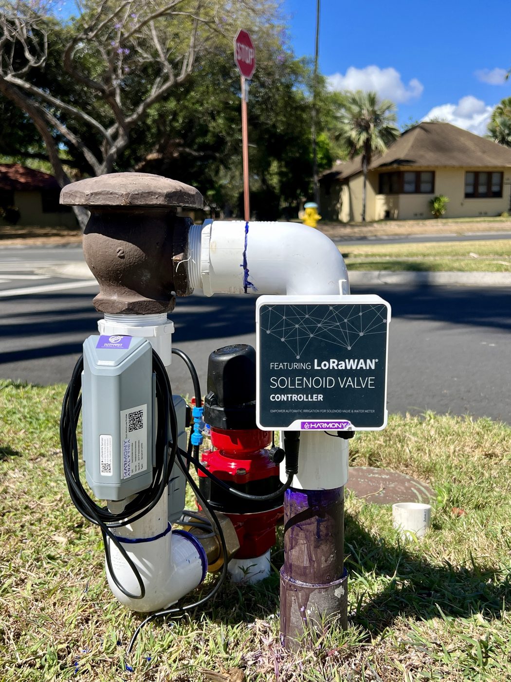
A municipal median retrofit.
Existing valves and meters, new wireless control, and a slit trench instead of an open cut.
Questions
Wireless irrigation, answered.
Does it work with the valves already installed?
Usually. The controller drives DC latching solenoids, which are available as drop-in replacements for the AC solenoids on most commercial valve bodies. The valve stays, the solenoid is swapped, and the controller's output voltage is set to match.
What happens to the schedule if the network goes down?
Nothing. Up to 16 schedule plans are stored on the controller and run on its own clock. An outage delays the reporting, not the watering. When the network returns, the stored states and counts are reported.
How fast does a manual command reach the valve?
At the next receive window. The controller runs as a Class A device: it listens briefly after each report, so a command waits for the next report or for the shorter response-time interval we set for manual control. Five minutes is a common choice for medians, which keeps the battery life measured in years. Scheduled runs never wait, because the schedule is on the controller.
How far can a controller be from the gateway?
Around a mile or two in a built-up corridor and much farther with line of sight. A gateway on a building roof or a light pole typically covers a district of medians. We survey coverage before the design is fixed.
Is there a monthly fee per valve?
Not on a private network. The controllers talk to your own gateways, and there is no cellular subscription per device. Costs are the hardware, the gateway backhaul and the platform.
Can it work alongside a conventional central control system?
Yes. Wireless zones report to MODURA, and the data is available over MQTT, a webhook or the API for a central control or asset management system. Many sites keep their wired zones as they are and add wireless only where the wire is the problem.
Harmony Analytica
Have a zone the wire can't reach?
Send us the site plan or a photo of the valve. We will tell you what it takes to bring it under control, and review a draft specification if you are designing it in.